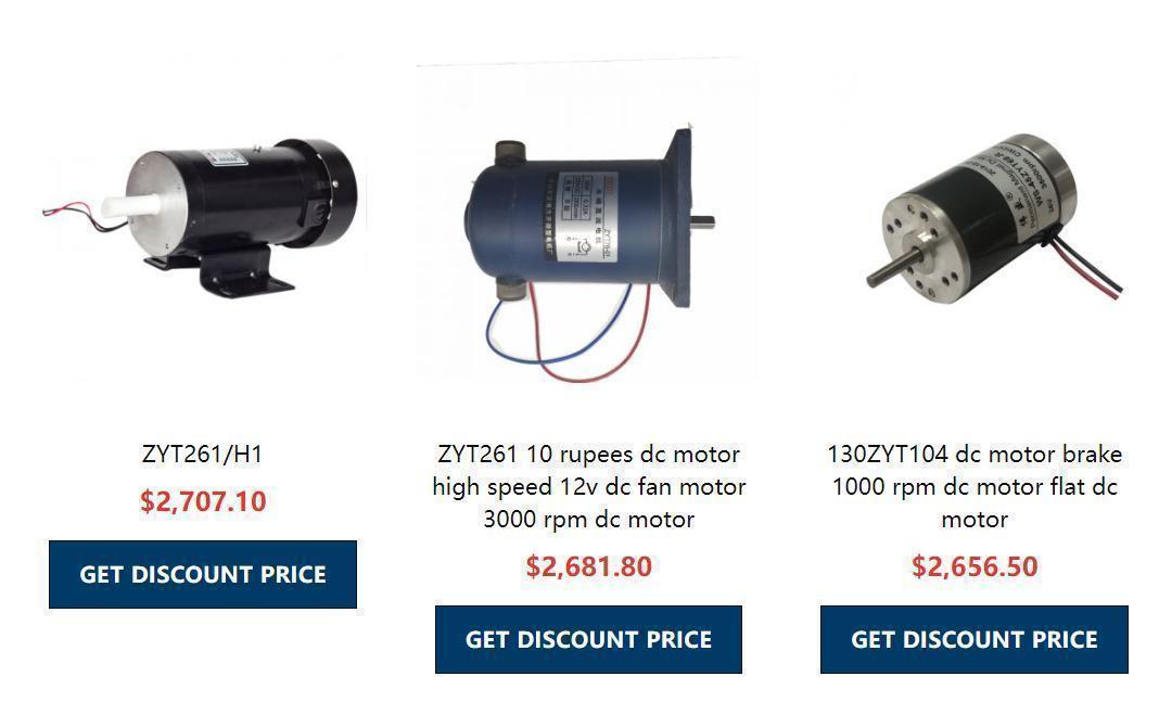
Ẹrọ DC jẹ ọkọ ayọkẹlẹ kan ti o yi agbara DC pada si agbara ẹrọ. Nitori iṣeṣe ilana ilana iyara to dara, o ti lo ni lilo ni awakọ ina. Ni ibamu si ipo igbadun, awọn ọkọ ayọkẹlẹ DC ti pin si awọn oriṣi mẹta: oofa titilai, igbadun lọtọ ati igbadun ara ẹni. Laarin wọn, igbadun ara ẹni ti pin si awọn oriṣi mẹta: inira ti o jọra, idunnu onitẹlera ati idunnu apọju.
When the DC power supply supplies power to the armature winding through the brush, the N-pole lower conductor on the armature surface can flow current in the same direction. According to the left-hand rule, the conductor will receive a counterclockwise torque; the S-pole lower part of the armature surface The conductor also flows in the same direction, and according to the left-hand rule, the conductor will also be subjected to a counterclockwise moment. In this way, the entire armature winding, that is, the rotor, will rotate counterclockwise, and the input DC electrical energy will be converted into mechanical energy output on the rotor shaft. It consists of stator and rotor. Stator: base, main magnetic pole, commutating pole, brush device, etc.; Rotor (armature): armature core, armature winding, commutator, shaft and fan, etc.
Ipilẹ ipilẹ
Divided into two parts: stator and rotor. Note: Don't confuse the commutator with the commutator.
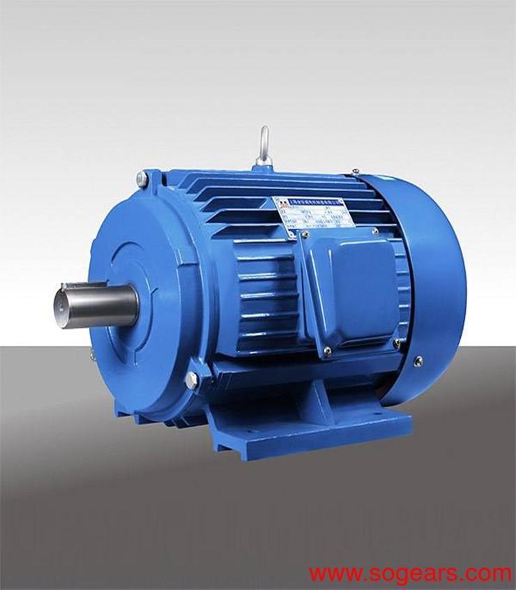
Awọn stator pẹlu: akọkọ oofa polu, fireemu, commutating polu, fẹlẹ ẹrọ, ati be be lo.
Ẹrọ iyipo pẹlu: mojuto armature, yikaka armature, commutator, ọpa, afẹfẹ, ati bẹbẹ lọ.
Tiwqn iyipo
Apakan iyipo ti ọkọ DC jẹ akopọ armature, armature, commutator ati awọn ẹrọ miiran. Awọn paati ninu igbekale ti wa ni apejuwe ni apejuwe ni isalẹ.
1. Apakan mojuto Armature: iṣẹ rẹ ni lati ṣafikun yikaka armature yikaka ati yiyipada ṣiṣan oofa naa, lati dinku pipadanu eddy lọwọlọwọ ati pipadanu hysteresis ni armature mojuto nigbati ọkọ ayọkẹlẹ n ṣiṣẹ.
2. Armature part: the function is to generate electromagnetic torque and induced electromotive force, and carry out energy conversion. The armature winding has many coils or glass fiber-coated flat steel copper wire or strength enameled wire.
3. The commutator is also called commutator. In a DC motor, its function is to convert the current of the DC power supply on the brush into the communication current in the armature winding, so that the tendency of electromagnetic torque is stable. In the generator, it transforms the electromotive force of the armature winding into the DC electromotive force output on the brush end.
The commutator is insulated with mica between cylinders composed of many pieces, and the two ends of each coil of the armature winding are separately connected to two commutating pieces. The function of the commutator in the DC generator is to convert the alternating electric heat in the armature winding into the DC electromotive force between the brushes. There is current passing through the load, and the DC generator outputs electric power to the load. At the same time, the armature coil is also There must be current passing through. It interacts with the magnetic field to generate electromagnetic torque, and its tendency is opposite to that of a generator. The original idea only needs to suppress this magnetic field torque to change the armature. Therefore, when the generator outputs electrical power to the load, it outputs mechanical power from the original idea, completing the function of the DC generator to convert mechanical energy into electrical energy.
sọri
Ọna igbadun
The excitation method of the DC motor refers to the problem of how to supply power to the excitation winding and generate the magnetomotive force of the excitation to establish the main magnetic field. According to the different excitation methods, DC motors can be divided into the following types:
1. Separately Excited DC Motor
There is no connection between the field winding and the armature winding, and a DC motor powered by other DC power sources to the field winding is called a separately-excited DC motor. Permanent magnet DC motors can also be regarded as separately excited DC motors.
2. Shunt Excited DC Motor
The excitation winding of the shunt-excited DC motor is connected in parallel with the armature winding. As a shunt-excited generator, the terminal voltage from the motor itself supplies power to the field winding; as a shunt-excited motor, the field winding and armature share the same power source, which is the same as a separately-excited DC motor in terms of performance.
3. Series Excited DC Motor
After the field winding of the series-excited DC motor is connected in series with the armature winding, it is connected to the DC power supply. The excitation current of this DC motor is the armature current.
4. Compound Excitation DC Motor
Compound-excited DC motors have two excitation windings: shunt excitation and series excitation. If the magnetomotive force generated by the series winding is in the same direction as the magnetomotive force generated by the shunt winding, it is called product compound excitation. If the two magnetomotive forces have opposite directions, it is called differential compound excitation.
DC motors with different excitation methods have different characteristics. In general, the main excitation modes of DC motors are shunt excitation, series excitation and compound excitation, and the main excitation modes of DC generators are separate excitation, shunt excitation and compound excitation.
Awọn ẹya ara ẹrọ
(1) Good speed regulation performance. The so-called "speed regulation performance" refers to the motor under certain load conditions, according to needs, artificially change the speed of the motor. The DC motor can realize uniform and smooth stepless speed regulation under heavy load conditions, and the speed regulation range is wide.
(2) Large starting torque. The speed adjustment can be realized evenly and economically. Therefore, all machines that start under heavy loads or require uniform speed adjustment, such as large reversible rolling mills, hoists, electric locomotives, trams, etc., use DC.
Motor drag.
There is no brush classification
1. Brushless DC motor: Brushless DC motor is the exchange of the stator and rotor of ordinary DC motor. Its rotor is a permanent magnet to generate air-gap magnetic flux: the stator is an armature and consists of multi-phase windings. In structure, it is similar to a permanent magnet synchronous motor.
The structure of the stator of a brushless DC motor is the same as that of an ordinary synchronous motor or an induction motor. Embed multi-phase windings (three-phase, four-phase, five-phase, etc.) in the iron core. The windings can be connected in star or delta, and connected to each power tube of the inverter for reasonable commutation. The rotor mostly uses rare earth materials with high coercivity and high remanence, such as samarium cobalt or neodymium iron boron, due to the different positions of the magnetic materials in the magnetic poles. It can be divided into surface type magnetic poles, embedded magnetic poles and ring magnetic poles. Since the motor body is a permanent magnet motor, it is customary to call a brushless DC motor also a permanent magnet brushless DC motor.
2. Brushed DC motor: The two brushes (copper brush or carbon brush) of the brushed motor are fixed on the back cover of the motor through an insulating seat, and the positive and negative poles of the power supply are directly introduced to the inverter of the rotor, and the phase is changed. The device connects the coils on the rotor, and the alternating polarity of the three coils is constantly alternately changed to form a force with the two magnets fixed on the housing to rotate. Since the inverter and the rotor are fixed together, and the brush is fixed together with the housing (stator), the brush and the inverter continue to rub against when the motor rotates, generating a lot of resistance and heat. Therefore, the efficiency of the brushed motor is low and the loss is very large. But it also has the advantages of simple manufacturing and low cost.
Change the direction of rotation of the DC motor
There are two ways to change the direction of rotation of a DC motor:
One is the armature reverse connection method, that is, keeping the terminal voltage polarity of the field winding unchanged, and the motor is reversed by changing the polarity of the armature winding terminal voltage;
The second is the reverse connection of the field winding, that is, keeping the polarity of the armature winding end voltage unchanged, and the motor can be adjusted by changing the polarity of the field winding end voltage. When the voltage polarity of the two changes at the same time, the rotation direction of the motor does not change.
Separately excited and shunt-excited DC motors generally adopt the armature reverse connection method to achieve forward and reverse rotation. Separately excited and shunt-excited DC motors are not suitable to use the field winding reverse connection method to achieve forward and reverse rotation because the field winding has a large number of turns and a large inductance. When the field winding is reversed, a large induced electromotive force will be generated in the field winding. This will damage the insulation between the blade and the field winding.

The reason why the series-excited DC motor should adopt the field winding reverse connection method to realize the forward and reverse rotation is because the voltage at both ends of the armature of the series-excited DC motor is relatively high, and the voltage at both ends of the field winding is very low, so reverse connection is easy. Law.
DC Motor manufacturers in China. DC motors use permanent magnets or electromagnets, brushes, commutators and other components. The brushes and commutators continuously supply external DC power to the coil of the rotor, and change the direction of the current in time to enable the rotor Continue to rotate in the same direction.
The principle of a motor and a generator are basically the same, and the direction of energy conversion is different. The generator converts mechanical energy and kinetic energy into electrical energy through a load (such as water power, wind power). If there is no load, the generator will not have current flowing out. The cooperation of electric motors, power electronics, and micro-controllers has formed a new discipline called motor control. Before using the motor, you need to know whether the power source is DC or AC. If it is AC, you also need to know whether it is three-phase or single-phase. Connecting the wrong power supply will cause unnecessary losses and dangers. After the motor is rotated, if the load is not connected or the load is light so that the motor speed is fast, the induced electromotive force is stronger. At this time, the voltage across the motor is the voltage provided by the power supply minus the induced voltage, so the current is weakened. If the load of the motor is heavy and the rotation speed is slow, the relative induced electromotive force is smaller. Therefore, the power supply needs to provide a larger current (power) to output/work corresponding to the larger power required.

The production process of brushless DC motors has certain requirements for speed control performance. To sum up, the editor of brushless DC motor manufacturers introduces the following three aspects for the speed control requirements of the speed control system:
1. Speed regulation, within a certain range of high speed and low speed, the speed can be adjusted in sub-gear (staged) or smoothly (infinitely);
2. Stable speed, stable operation at the required speed with a certain accuracy, and no excessive speed fluctuations under various interferences to ensure product quality;
3. Equipment with acceleration/deceleration, frequent starting and braking requires acceleration and deceleration as fast as possible to improve productivity, and machinery that is not suitable for drastic speed changes requires starting and braking as smooth as possible.
In addition, for the first two requirements, two speed control indicators are defined as "speed control range" and "static difference rate".
The mechanical requirement is that the brushless DC motor provides an AC speed range of the ratio of high speed to low speed. The motor has high and low speed at rated load. For machinery with very light load, it can achieve high and low speed at load.
Static difference rate: When the system is running at a certain speed, the ratio of the corresponding speed when the brushless DC motor load increases from the ideal no-load to the rated value and the ideal no-load speed is called the static difference rate.
The static difference rate is used to measure the speed stability of the speed control system when the load changes. It is related to the hardness of the mechanical characteristics. The harder the characteristic, the smaller the static difference rate, and the higher the stability of the speed.
